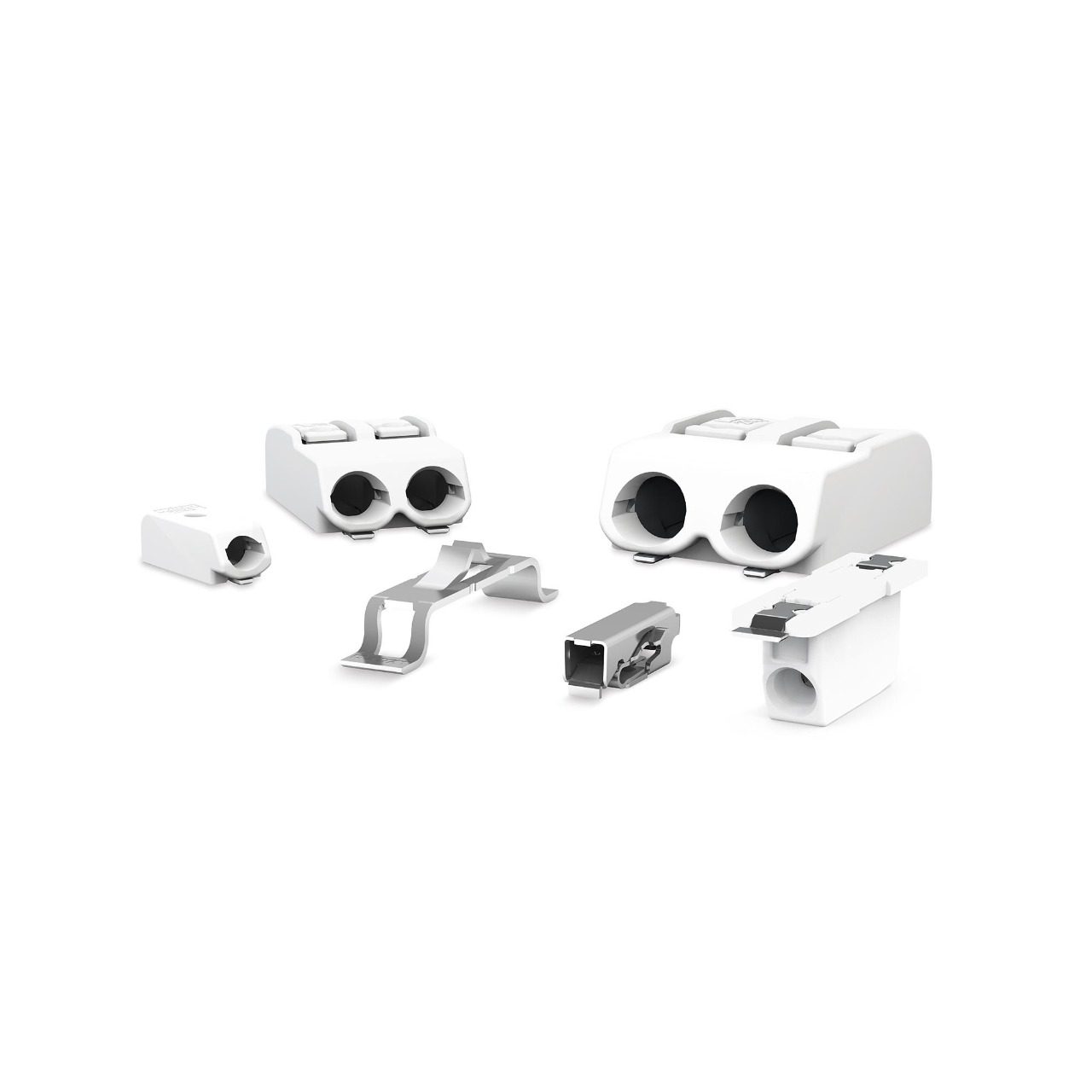
Like most engineers, you probably have a collection of breadboards scattered around your lab. Maybe you’ve even got a few SMD connectors that you need to use from time to time. But connecting these devices can be challenging, especially if you don’t have any wires! That’s where breadboards come in handy – they let you easily connect circuits so that you can test the connections before making them permanent. In this article, we’ll show you how to use SMD connectors with breadboards so that you can build more complicated circuits without having to resort to soldering!
First, decide which type of connector you need. You’ll need to make three main types of connections with a breadboard: male, female, and male-to-female.
Male connectors: These connectors have a pin on one end and a hole on the other. You can use these to connect wires from one component to another.
Female connectors: These connectors have two pins, and they can be used to connect wires between two components.
Male-to-female connectors: These connectors have three pins and can be used to connect wires between two components in either direction.
Next, connect the male connector to the first wire on your breadboard and the female connector to the second wire.
Now, connect the male-to-female connector to the wires you want. For example, if you wanted to connect pins 1 and 3, you would use the connector.
Finally, connect the connector’s other end to the component you want to connect it to.
That’s all there is to it! You can now use SMD connectors with a breadboard and make custom cables to connect components.
If you’re ever lost or need a quick guide on using a particular component, check out our tutorials section. We’ve got guides on how to use all types of features, from microcontrollers to LEDs.
What are SMD connectors?
SMD connectors are miniature connectors used with breadboards. They are available in a combination of colors, and they can be easily inserted into the breadboard. SMD connectors allow you to connect wires between the breadboard pins without removing the board from the chassis.
If you’re looking to get started with SMD (surface-mount devices), breadboards are a great way to do so. Here’s a guide on how to use SMD connectors with breadboards.
Types of SMD
There are many types of SMDs. Here are the most common:
Trenching: This feature makes it easier to drill through a PCB or other surface. It often has multiple channels that guide the drill bit, making it faster and more accurate.
Microvia: This is a minor feature connecting two PCB parts. It’s often used to route power or signal lines.
Gullwing: This type of via has an inward-pointing wing on one side. It helps keep the via clean and allows for better electrical connection.
Features of SMD
There are many types of SMD features, and each has its benefits. Some of the most common types of SMD features include:
Through-hole Features: These features are inserted through a hole in the PCB. They are typically used to route signals or power cables.
SMT (Surface Mount Technology) Features: These features are mounted onto the PCB using a small machine called an “SMT tool.” This type of feature is often used for higher-volume production applications.
Embedded Features: These features are embedded into the PCB. They can be used to control the board’s power and signal levels or provide connectivity between components.
Advantages of SMD
- Increased reliability and robustness of the products.
- Lower product cost due to reduced number of parts and less processing time.
- Improved productivity as fewer errors are made during the manufacturing process.
- Reduced obsolescence risk as products can be upgraded or modified without replacing entire components.
- Faster time-to-market for new product designs as a simplified assembly is possible.
- Enhanced customer satisfaction as products are more reliable and easier to use with fewer functional limitations.
- Greater flexibility in manufacturing processes, allowing for unique configurations not possible with traditional PCBs and other Printed Circuit Board (PCB) technologies.
- Reduced environmental impact as products can be manufactured using less waste material, and energy resources are used less overall in the manufacturing process.
Conclusion
Like most engineers, you’ve probably been using surface mount devices (SMDs) in your designs for a while now. But have you ever used breadboards to prototype them? If not, it’s time to learn how! Breadboarding is a great way to test and debug your designs without worrying about damaging the SMDs. In this article, we’ll show you how to use SMD connectors with breadboards so that you can build complex prototypes quickly and easily.
If you have queries or comments, please feel free to leave them in the remarks section below.
Thanks for reading!

